The Beam Engine Story by John Jasper
A phone call from Mr Douglas Ross, the Town Clerk of Trowbridge on the 15 th of January 1992 to Jill Taylor the Director of Coldharbour Mill was the beginning of the most interesting challenge in my engineering career. The mill museum had a beam engine house with no engine in it whereas Trowbridge Council had a beam engine on its hands but could not justify the expense of housing it with a boiler to run it. The Science Museum had been instrumental in saving the engine from the scrap man when the brewery was demolished and stipulated that when it was erected it must be run on steam, not air, motored electrically or as a static display. stipulated that when it was erected it must be run on steam, not air, motored electrically or as a static display.
The engine is probably the only remaining beam engine built by Kittoe and Brotherhood at their works under the railway arches at 53-56 Compton Street, Islington, London, in 1867. Peter Brotherhood was the son of Rowland who amongst other things was contracted to Brunel working on the Great Western Railway as a civil engineer employing up to a thousand men digging the famous Sonning cutting. It was Rowland and his men who Isambard called on to cut out the masonry when the Great Britain had to be freed from the dock at Bristol in December 1884 after her launch. As you can see Peter Brotherhood was born in 1838 into a family deeply involved in the developing world of engineering of the day. He worked in his fathers railway works at Chipenham, the G.W.R. works and then in the employ of Maudslay Sons and Field in Lambeth, the foremost engineering company in the country. He went into partnership with Mr. G. D. Kittoe during 1867, so this beam engine may well be the very first one built by the company. Mr. Kittoe retired in 1871and Peter`s next partner was Mr. Hardingham until 1878 when Peter became sole proprietor of the company which still exists today under his name in Peterborough.
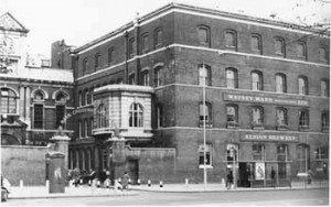
The engine was built for the Albion Brewery of Mann Crossman and Paulin in Whitechapel in London. By the way it made a couple of brief appearances in the recent television programme “How London Was Built” presented by Adam Heart-Davis in the episode about entertainment and the brewing industry. Later on in its history to increase its power supply the brewery installed a 24”x 42” horizontal single cylinder “pusher” engine on the other end of the same crankshaft built by Robert Morton of Stockton-on-Tees. Both engines ran on full boiler pressure with the exhaust steam used in the brewery for heating the mash tuns etc. Power was taken off by large cast iron gears, one wheel having cast iron teeth and the next having wooden cogs, alternating thus up through the building. This we are told gave a relatively quiet and smooth running system. The engine was in regular use until 1934 when a cracked bedplate forced its retirement. Those of you familiar with casting design will notice the sharp internal corners in the bedplate and other castings around the engine thus making them susceptible to localised stress and cracking.
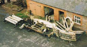
The engine was offered by Watney Mann to Trowbridge Town Council in June 1978 for their new museum. Dismantled by Historic Steam Ltd., part of Kew Bridge Engine Trust, and stored at Bradford-on Avon. In January 1989 it was moved to Trowbridge and later to Westbury where we saw it for the first time on a disused trailer under a tarpaulin at Rygor`s Transport yard.

It was donated free of charge to Coldharbour Mill Trust but needed transporting to the mill. The Friends of Coldharbour Mill could see that this was an opportunity not to be missed and paid the £1070.00 needed to get the engine parts to their final home.
Early April 1992 saw the engine parts arrive by Wheelers Transport in the mill yard, as usual there were those that said “that`s brilliant” and some said “it`ll never run!”- well you can`t please everyone all the time. We were told
that the bearing brasses and stop valve were still being looked after at Kew Bridge so Jill Taylor the museum director, and myself went up there to collect them, and were treated to a good look round by Ron Plaster who was one of the team that rescued the engine.
That was early May and on the 6th June we picked up the Beddoes displacement lubricator and nameplate from Trowbridge Museum.
The Mill Museum had already applied for listed building consent to build a beam engine in a beam engine house! This was granted in August 1992 and having surveyed the original engine foundations for the Science Museum`s archives work began in earnest on 9th January 1993 on the new engine foundations.
In anticipation of having to lift heavy masonry and machinery we had already looked at the original timber lifting beams in the roof of the engine house and decided that new steelwork was required. Some second hand steel beams were donated by Jerry Stoneman, my boss and steam enthusiast. He introduced me to the mill museum in the first place by saying “Hey Jonny, there`s a lovely old steam engine down the road that ought to be got going.” This was back in November 1990 and referred to the 300 horse power Pollit and Wigzell cross compound mill engine that started my volunteering days at the mill. We installed the lifting steels and had them tested to 4 tonnes S.W.L.
The original pits around the brick and stone foundation were 11 feet deep. A planning application was made to lower the floor level by about 2 feet to allow a level access from the boiler house and to give us room for the new flywheel under the viewing gallery in the middle of the building. (Yes, we had to get planning permission to put a beam engine in a beam engine house)!!

A structural engineer was engaged to design the new reinforced concrete foundations and to accommodate them we had to move large blocks of the original stonework lowering them into the pits to fill the unwanted voids. We toiled at this as well as removing vast quantities of brickwork for twelve months until the 11th January 1994 when all was ready to start the concrete work.
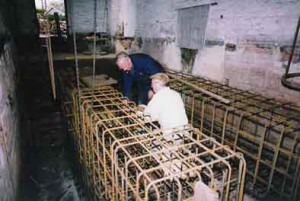
We mixed 20 tonnes of lean mix concrete to complete the void filling – hardcore was not an option! Meanwhile during my spare evenings at home I was on a “teach myself course on reinforced concrete formwork”, I found this an interesting challenge. While some of us were working on the foundations the rest of the volunteer group were cleaning up and conserving the smaller bright wrought iron parts of the engine. Two tonnes of reinforcing bars of all shapes and sizes were assembled, and three separate pours of C30 concrete totalling 60 tonnes made up the complete foundation.
It was now September 1995 and we were all very pleased with the end result. Mr Roy Middleton, a local business man, owned a mobile grit blasting unit and offered to grit blast and prime all the castings. Sadly he passed away before he could see the engine built but his widow and son James honoured his promise to help. James and ourselves spent the hottest weekend of the year doing the job – not a pleasant task for James inside his protective suit and helmet!


Whilst at the Bishops Lideard steam rally driving Gerry Stoneman`s Foden steam wagon it was decided that it would be a good idea to have a photograph of the engines present that had worked from King`s yard just across the road, as the site was about to be developed for housing. While we were there I had a look around in the derelict corrugated iron sheds and noticed an old hand operated overhead gantry crane and saw that it had a 4 ton Morris chain block on it, just the thing for the beam engine house! The developers were persuaded to part with it and ten pounds worth of new operating chain put it right. The wheel assemblies of the gantry were recycled and readily converted into a heavy duty demountable trolley for moving large engine parts around the yard and in the engine house.
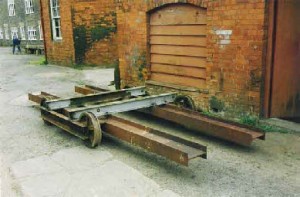
Many suggested that the engine parts could be craned in through the roof of the engine house but funds did not allow for this and besides the challenge of building the engine the old fashioned way was not to be missed. As the bedplate was rather delicate we dug a shallow pit underneath and assembled the trolley beneath it then winched it out across the yard to be grit blasted. Once we got the bedplate into the boiler house we put a needle through the narrow doorway and cut out the brickwork each side so that we could pull it through to its final resting place.
Peter Brotherhood of Peterborough offered excellent support and though no spares were available for possibly their very first product they made up new holding-down bolts for it. Much interest was shown at the works when we sent the piston rod up there to be skimmed which was done with no charge, even though the guarantee had run out over 120 years earlier! I call that real customer care.
Having bolted the the bedplate down work started on engine building with much enthusiasm. The columns and entablature were first to go up giving quite a classical look to the structure followed by the trunnion bearings and sway beam. Everything was assembled and set up using straight edges, plumb bobs, spirit levels and lots of patience.
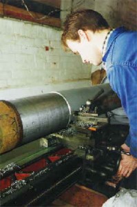
The crankshaft with the pusher engine crank on the other end was too long to accommodate in the engine house so permission was sought from the Science Museum to shorten it. Permission was granted and presented us with the problem of machining the three ton shaft! We would need to machine a new bearing surface on the crankshaft as it has sunk bearings fitted and as there are no heavy engineering facilities in the area I decided that we should do the job ourselves. We started building a makeshift lathe.
Using some second hand steel beams a frame was made up to support the original crankshaft pedestal bearings and the crankshaft 

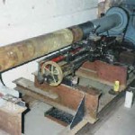 was eased into place. A geared electric motor was fitted to the frame and a couple of vee-belts were fitted around the governor drive pulley already on the shaft.
Heavy damper weights from the front of the spare
Lancashire boiler were lashed into timber frames to act as a counterbalance the uneven weights of the two cranks. Finally a small lathe bed was bolted to the frame to machine the new bearing area. The electric motor was not quite powerful enough to start the shaft turning on its own so a hearty push on one of the cranks was always required to give it a start.
Being made of wrought iron the shaft was quite different to machine than steel, but by adjusting the tool angles and reducing the cutting speed we ended up with a good finish. A steady was made and the shaft parted off with a 9” disc cutter and then a piece of metal bandsaw blade in a large bow saw frame.
Meanwhile others in the group were cutting out a recess in the wall to house the outrigger bearing, casting the padstone and building the brick arch. Having blued and scraped the bronze bearings to the crank the pedestals, bearings and crankshaft were fitted, more use of plumb bobs, spirit levels, straight edges and patience!
The flywheel consisted of a hub in two halves with four spokes on each half and the rim was in four pieces held together with large square pegs and cross wedges. It looked as if one half could be built in the pit and the other fitted on top. But upon detailed investigation it was found that in keeping with good engineering principles the joint line of the rim did not line up with the one in
the hub.
So we proceeded to build the rim using quantities of steel and timber to position it exactly in its final alignment to the crankshaft. The spokes were then wedged together on the shaft and jacked into the rim. The original spoke bolts had been gas-cut out so new ones had to be made, this was kindly done free of charge by Hepco Slide Systems of Tiverton.
The connecting rod was then fitted and work proceeded on fitting the cylinder, piston, piston rod and crosshead assembly. The beautifully made parallel motion was then assembled and many hours were spent setting it up to run correctly. The others in the team were turning the twelve tonne fly wheel by hand (and their own weight), and were to hear me call “just one more turn” many, many times. James Watt was rightly proud of his parallel motion, it is a most elegant mechanism to watch. The rest of the engine went together very well, the colour was established from traces of original paint found inside the entablature casting, the whole engine had been painted white during its last years at the brewery.
The original displacement lubricator was made by Beddoes of London, the air cooled condenser chamber is on the left and supplies its condense to the oil chamber in the centre. A pipe inside this chamber takes oil floating on top of the water down to the base of the sight glass where it is regulated by the valve bottom right and through a nozzle onto a central wire in the sight glass. As the sight glass is full of water the oil globule ascends the wire to the top and on into the steam supply to the valve chest. One filling of the oil chamber lasts about four hours delivering one drop every ten seconds.

We had the first run of the unfinished engine on the 23rd September 1997 and though a little tight it ran at about 16 RPM on 40 PSI of steam. Finishing work carried on until the 31st December 1997 when it was run publicly for the first time.
Coldharbour Mill Museum now has a rare collection of working historic prime movers covering a large period of the industrial age. The early breast shot waterwheel of 1821, the Brotherhood beam engine of 1867 and the Pollit and Wigzell horizontal cross compound mill engine and rope race of 1910 which worked commercially until 1982 when the mill stopped production.
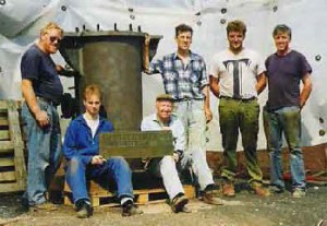
don`t think that it is out of place to mention the volunteers that devoted a lot of time, effort and skill to make this project a success. The bulk of the work was done by myself, John Babb, Andy Horner, Gerry Tottle, Alan Hunt, Geoff Hayden, Mike Perkins, Rob Brotherston, Martin Hawkins, Jack Atkinson and my son Trevor Jasper. Many others have also contributed to the project incuding Alan Bainton, Bill Douglas, Dave Atkinson, Evan Boardman, Steve Kingett, James Hodgeson, David Sprague, John Palmer, Frank Scrace, Hannah Thomas and many more. I recorded a total of 4524 man/hours donated by these people. I enjoyed every minute of it and I hope they did.
By John Jasper