The Mill Chimney

The Mill Chimney

At 38.4 metres this is the second chimney at the site.

The lower section is double skinned to give it strength and stability. Bonding the brickwork with lime mortar gives it flexibility enabling it to withstand high winds.

Two lightening conductors have been fitted.


Lancashire Boiler

Lancashire Boiler

Our working boiler is a 1910 Galloway boiler installed at the same time as the Pollit and Wigzell engine. This is a prime example with plain furnace tubes. We also have a secondary boiler in preservation.

In each of the two furnace tubes is a grate that extends six feet back to a brick wall with a gap at the top to allow the hot gasses to be drawn along the tube to the back of the boiler. At the far end of the boiler there is a brickwork chamber which directs the gasses down to a flue which brings them under the middle of the boiler to the front behind the brown glazed brick wall. At this point the gasses are split and sent down a flue at either side of the boiler shell to the dampers and the outside flue down to the chimney. This “three pass” system of flues ensures that the majority of the boiler surface area is exposed to the heat generated by the fires thus increasing efficiency.

The large weights suspended on wire ropes at the front of the boiler counterbalance the large plate dampers at the far ends of the side flues. These are raised and lowered to control the rate of combustion of the two fires. The most important factor in boiler management is knowing and controlling the water level within the vessel. In the two vertical brass gauge frames on the front plate there are thick glass tubes which show the operator the current water level. The pressure gauge at the top of the front plate indicates the steam pressure within the boiler.

Behind the pressure gauge on the top of the vessel is the deadweight safety valve which releases excess steam to prevent damage to the boiler and the resulting danger.

The crown valve isolates the boiler from the steam pipework supplying the engines and pumps on the site. Further along the boiler is the water level alarm which is a float operated device that automatically gives warning of too high or too low water level and also acts as a second pressure safety valve. The large round manhole provides access to the inside of the boiler from the top. You will notice a smaller oval access manhole at the bottom of the front plate of the boiler as well.


Kittoe and Brotherhood Steam Engine

Kittoe and Brotherhood Steam Engine

Built for the Albion Brewery and saved from scrap it now brings life to the once empty Beam Engine House.

Through the doorway from the boiler house you will see the beam engine. This engine built in 1867 by Kittoe and Brotherhood is a fine example contemporary with the first steam engine on this site dated 1865.

The design employs several concepts used in early engines, the most obvious is the sway beam and upright cylinder. Early designers thought that the weight of the piston would wear its way through the bottom of a horizontal cylinder, this may not be too far from reality as early lubrication methods and materials were very crude.

This engine employs a throttle valve to control its speed whereas later engines varied the point at which the steam was cut off along the stroke of the piston. In the Pollit and Wigzell engine the inlet and exhaust valves are separate and run at different temperatures but in this engine the steam goes in and out of the cylinder through the same passages and valve thus trying to heat it up and cool it down constantly, leading to inefficiency.

This engine has an excellent example of a watt type governor controlling its speed and his very elegant parallel motion keeping the piston rod moving in a straight line while the end of the sway beam moves in an arc. Bearing lubrication is by sight glasses and siphon pots while the piston is fed with heavier oil by a “Beddoes” displacement lubricator with a hydrostatic sight glass. Unlike the original engine this is not a condensing engine as the exhaust steam used to be used in the brewery to heat products in the brewing process.


More Steam

Wider Steam Collection

There are also a number of other steam items of interest – including an Ashworth Fire Pump, Marshall Engine and Tangy Engine as well as drive pulleys throughout the Mill.

The Ashworth Fire Pump

This duplex steam pump housed in its own building outside the boiler house has a “banjo” type rod mechanism, It drew water from the leat by the water wheel and pumped it into the hydrant main around the mill site, also up the rising main in the main stair of the mill building.

Although it is badly frost damaged it has been reassembled to appear to be in working order.

The Marshal Engine

The inverted vertical engine at the far end of the beam engine house was built by Marshals of Gainsborough in Lincolnshire and features a Pickering governor making it suitable for generating.

It has been connected to a converted DC electric motor used as a generator and demonstrates the conversion of steam pressure to electricity.

Tangye Engine

No history is known of this small horizontal engine built in Birmingham. It seems to have been in its present location for a long time and is assumed to have driven the carpenter`s lathe, drill and grindstone.

Beam House Engine Drive Pulleys

You will notice various flat belt pulleys above the beam engine, these were installed after the original beam engine was scrapped. The twin pulleys above the sway beam against the side wall were driven by the Pollit and Wigzell engine next door and drove the overhead shaft by the cylinder. Flat belts then transmitted the power down to two generators on the floor where the beam engine is now.

The Three Cylinder Feed Pump

In the corner of the boiler house is the original Pollit and Wigzell boiler feed water pump that was supplied with the engine and boiler as a complete installation. It is driven by a “fast and loose” flat belt pulley system from the compound mill engine. It has suffered frost damage at some time but we have patched it up enough to be able to pump cold water from the condenser waste up to a header tank in the roof This tank then supplies the water heating tank on top of the wall beside the 1910 boiler by gravity.


Pollit and Wigzell

One of the few surviving examples in the country.

It is a cross compound condensing engine supplied new to the mill for £1,810 in 1910, (£218,000 at 2019 prices).

Originally developing 240 HP at 88 revs per minute the engine was later up rated to 300 HP and was the main power source for the mill until closure.

High pressure cylinder 14.5” diameter x 42” stroke. Low pressure cylinder 27” diameter x 42” stroke.

Working principle

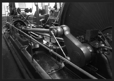
Steam from the boiler next door is admitted into the right hand cylinder and expands pushing the piston to and fro powering the rig
ht hand crank next to the flywheel.

The lower pressure steam is then exhausted through a large pipe under the floor to the left hand cylinder where more expansion pushes the piston and crank to the left of the flywheel.

This cylinder exhausts into the jet condenser by the engine house door where a vacuum is produced providing a 12% increase in the efficiency of the engine.

wpa9e621b5 wpc38e802b

Lubrication

The pistons and valves are lubricated with steam cylinder oil, a heavy oil that is fed into the steam supply to each cylinder, atomised by the heat and carried around the moving parts. Attached to the low pressure cylinder is the brass twin cylinder steam cylinder oil pump driven by a leaver and ratchet from the exhaust valve eccentric rod.

All other moving parts are lubricated by various types of oiler positioned around the engine that are topped up by the engine driver. The crankshaft bearings are each supplied with oil pumped from a small tank into the “aquarium” above each main bearing from where it drops into the bearing

Flywheel and crankshaft

The cranks are set at 90 degrees to each other on either side of the flywheel which weighs about 12 tonnes. The spokes of the flywheel have been boarded in to reduce windage in the engine house.

Grooves machined in the outer rim carry cotton drive ropes which transmit all the power developed by the engine to different size pulleys on each floor of the mill.

This drive system is housed in what is called a “rope race” built on the end of the mill building. (This rope race is a rare surviving example).

Valve gear

The inlet valves on top of the cylinders are known as drop piston valves. These are pistons working in a cylinder with ports around the bottom which are uncovered by lifting the piston, thus allowing steam into the cylinder.

Condenser

Inside the hollow casing of the condenser there is a single acting piston connected to the low pressure piston.

It works in a cylinder with non-return valves at the outer end (by the engine house door) and a ring of ports at the low pressure cylinder end.

Barring Engine

One side of the flywheel has gear teeth around the edge. Engaging into these with a sliding pinion enables a small single cylinder inverted vertical engine to turn the flywheel to the starting position or for engine maintenance, valve adjustment, or the like.

It is called a barring engine because it replaces the use of a long bar inserted in holes around the flywheel to turn the engine by hand.